


Energy Storage Cabinet High-Voltage Box Fails to Power On? A Senior O&M Engineer Guides You Through Troubleshooting
Release time: 2026-02-02
Contents
In the field operation of energy storage cabinets, the failure of the high-voltage box to power on is a common fault affecting system commissioning. Based on JNTech’s years of field experience, this article provides a comprehensive troubleshooting and maintenance solution for the high-voltage box power-on failure, covering everything from network cable communication and control board diagnostics to internal fuse and voltage measurements, helping you quickly restore system operation.
Prioritizing Efficiency and Safety in Emergency Repairs
The high-voltage box, as the core control hub of the energy storage system, will cause the entire system to shut down if it fails to power on. Quickly locating the fault point can not only significantly shorten downtime but also effectively reduce maintenance costs. However, when dealing with complex electrical circuits, standardized troubleshooting procedures are crucial to ensuring the quality of inspection and maintenance.
Safety Precautions: Life-Saving Measures Must Be Followed
High-voltage work is extremely dangerous. We solemnly remind you:
- Qualification Requirements: All operations are limited to personnel who have received professional electrical safety training and hold relevant certificates.
- Personal Protective Equipment (PPE): Insulating gloves, insulating shoes, and safety glasses must be worn.
- Power Disconnection Verification: Before disassembling any high-voltage components, you must ensure that the system is completely powered off and perform a compliant power verification procedure.
- Legal Compliance: Please strictly comply with local electrical construction safety regulations.
Phase One: Network Cable Communication Troubleshooting
Communication interruption is often the primary reason for the “unable to power on” false indication in the high-voltage box.
- Wire Sequence Check: Ensure all communication network cables comply with the 568B standard. Check that the wire sequence at both ends of the connector is exactly the same.
- Physical Link Test: Use a professional cable tester or test box to perform continuity tests to confirm whether there are broken wires or loose connections.
- Interface Inspection: Check the network port sockets on the high-voltage box and battery pack for bent pins, dirt, or oxidation.
- Replacement Verification: Try connecting directly with a known good standard network cable and observe whether the communication light status is restored.
Phase Two: Host Computer and Slave Control Acquisition Board Troubleshooting
When the physical link is normal but still cannot be recognized, we need to use host computer diagnostic tools.
- Software Access: Connect to the system via a LAN ↔ USB serial port box and open the diagnostic software.
- Error Localization: Focus on the Slave_ERR (slave error) flag. If a specific numbered packet does not return data, the specific slave control acquisition board fault can be located.
- Replacement Steps:
- Completely disconnect the system power and all sampling terminals. 2. Disconnect the network cable and remove the faulty board.
- After replacing the slave control acquisition board with a new one, reconnect the wiring harness and power on for verification.
Phase Three: Internal Sampling Line and Battery Module Inspection
Missing or abnormal sampling data can trigger BMS protection, preventing the high-voltage box from closing.
- Wiring Harness Inspection: Check the connecting harnesses between modules for loose pins, broken wires, or poorly crimped terminals.
- Module Correspondence: Confirm that the connection order of A/B modules matches the system configuration.
- Plug and Unplug Operation: For suspected poor contact points, perform a “re-plug” operation after power off to ensure tight contact of the metal terminals.
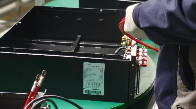
Phase Four: High-Voltage Box Internal Component Troubleshooting
If the control logic is normal but the main circuit is not working, further investigation of the high-voltage box is required.
- P+/P- Voltage Measurement: Use a multimeter to measure the voltage at the high-voltage output terminals (e.g., 48V – Example/To be localized).
- Fuse Detection: Before fuse replacement, measure its resistance. If it is infinite, it means the fuse is blown and needs to be replaced with a spare part of the same specification.
- 18650 Battery Maintenance: Check the voltage of the 18650 backup battery on the main board (e.g., 3.7V – Example/To be localized). If the voltage is too low, the main board logic will not start, and it needs to be replaced promptly.
Phase Five: Battery Pack and Busbar Inspection
- Terminal Voltage: Measure the voltage of each battery pack terminal to ensure the overall voltage difference is within the allowable range.
- Tightening Inspection: Check if the series copper busbars or busbar screws are loose. Loose connections can cause excessive voltage drop during power-on.
- Abnormality Determination: If an abnormal single battery pack voltage is detected (e.g., 0V – Example/To be localized), it is recommended to stop powering on and contact technical support for further evaluation.
Phase Six: Reset and Verification Process
After completing component repair or replacement, the system must be restored in the correct order.
- Physical Reassembly: Reinstall the high-voltage box cover and protective structure. 2. Wiring Sequence: Connect the P- (negative terminal) and P+ (positive terminal) in sequence, then insert the control cable and network cable.
- Power-on Observation: Observe the indicator lights on the panel.
- Power Indicator: Constantly lit.
- Operation Indicator: Flashing green or constantly lit.
- Fault Indicator: Off (normal operating state).
On-site Maintenance Checklist and Quick Reference Guide
Troubleshooting Checklist
| Fault symptoms | Recommended initial inspection procedures |
|---|---|
| The high-voltage box shows no indicator lights | Check the voltage of the 18650 battery and the main fuse |
| Battery pack not found | Remake the network cable and check the ID DIP switches |
| The host computer displays Slave_ERR | Replace the slave acquisition board corresponding to this number |
| The circuit breaker tripped the moment the power was turned on | Check the tightness of the busbar screws and for any short circuits. |
Recommended Maintenance Schedule
- Daily Check: Observe the operating indicator lights and record any abnormal alarms.
- Weekly Check: Check if the ventilation ports are blocked and check the host computer data for pressure difference fluctuations.
- Monthly Check: Randomly check the security of the communication network cables and clean dust from the outside of the enclosure.
Required Tools and Consumables List
- Measurement Tools: High-precision multimeter (supports DC 1000V+), cable tester.
- Safety Tools: 1000V insulated gloves, insulated torque wrench.
- Spare Parts: Cat5e shielded network cable, spare slave control acquisition board, DC fuse, 18650 spare battery.
Common Mistakes and Avoidance Suggestions
- Blindly replacing parts: Directly replacing expensive slave control boards without troubleshooting the physical network cable link often leads to unnecessary increases in maintenance costs.
- Hot-swapping: It is strictly forbidden to hot-swap the sampling terminals, as this can easily cause electrostatic discharge or surge damage to the BMS chip.
- Ignoring screw torque: Tightening busbar screws only by feel, without reaching the specified torque, can lead to overheating and fire during subsequent operation.
Conclusion
Although the high-voltage box power-on failure is a tricky problem, most issues can be resolved on-site by following a scientific troubleshooting logic. If you encounter any logical errors that you cannot resolve during operation, or require the latest host computer diagnostic software and original spare parts, please feel free to contact the JNTech technical after-sales support team.
For more maintenance tutorials, please continue to follow our official YouTube, LinkedIn, and Facebook channels.
Web: www.jntechenergy.com 丨 WhatsApp: +86 18019566616 丨 Email: info@jnnewenergy.com